
Sizing 10kV outdoor line compensation: Step-by-Step Guide
2026-10-13 17:28:57
When engineers and procurement managers ask about sizing 10kV outdoor line compensation, the answer starts with one core principle: match reactive power capacity to actual line demand. A properly sized outdoor reactive power compensation unit on a 10kV distribution feeder can raise the power factor to ≥0.95, reduce I²R losses by 10–30%, and stabilize terminal voltage on lines exceeding 10 km. This guide walks through every step — from load assessment to supplier selection — so you can confidently specify the right equipment for rural grids, agricultural networks, or industrial feeders.
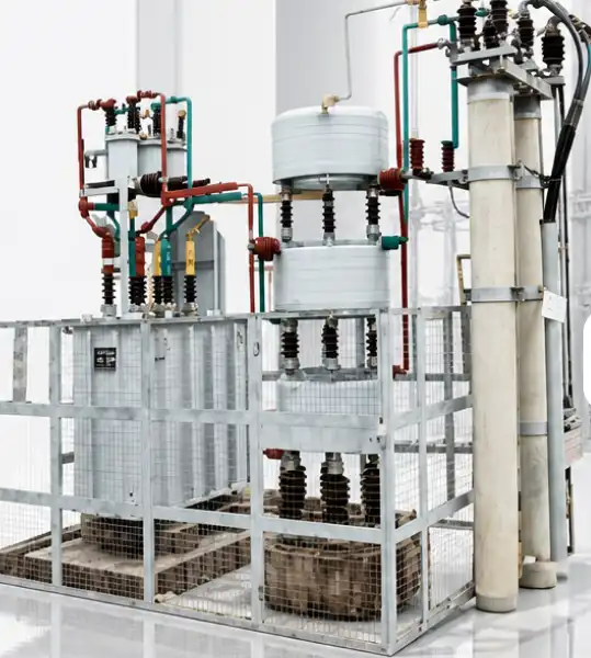
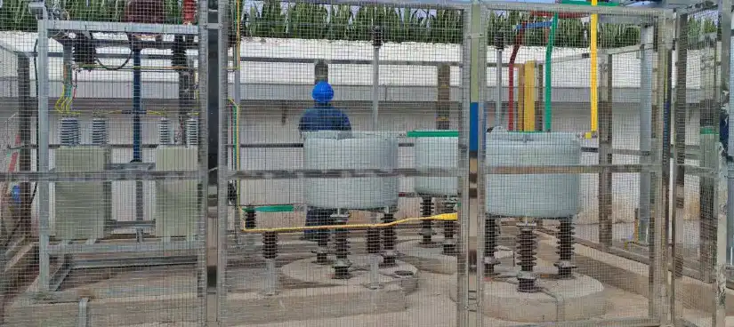
Understanding the Principle and Benefits of 10kV Outdoor Line Compensation
How Reactive Power Affects Distribution Lines
Motors, transformers, and irrigation pumps are examples of inductive loads that use lagging reactive power, which puts a lot of stress on distribution feeders. On a 15-kilometer rural 10kV line, this effect makes the voltage drop below the ±7% range required by grid codes at the far end. Putting up pole-mounted capacitor banks at the 2/3-point of the feeder adds capacitive reactive power, which fixes the imbalance at the source instead of at the substation.
Core Technical Parameters
The outdoor line correction items from Xi'an Xikai can handle rated voltages of 6 kV, 10 kV, and 35 kV, and each bank can hold up to 100 Mvar. All-film dielectric capacitors have loss rates below 0.2 W/kvar, which is well within the limits set by IEC 60871. Built-in series reactors, which usually have an impedance of 6% or 12%, tune the circuit to avoid 5th and 7th harmonic resonance, which is a common issue in grids that feed variable-speed drives or green inverters.
Measurable Benefits in Real-World Networks
A study from the State Grid Corporation in 2022 found that adding reactive power to 10kV country lines cut distribution losses by an average of 18% and brought end-of-line voltage within acceptable limits for 94% of tracked feeders. Power factor corrections between 0.75 and ≥0.95 directly lower the apparent current in conductors. This makes cables and transformers last longer and lowers energy bills for grid operators who are trying to make the most of limited funds for technical improvements.
Step-by-Step Process for Sizing 10kV Outdoor Line Compensation
Step 1 — Assess Load Profile and Reactive Power Deficit
First, get measuring data from the pump every 15 minutes for at least 30 days, spanning the busiest times for farming or industry. How to find the reactive power deficit? Q = P × (tan φ₁ − tan φ₂), where φ₁ is the current power factor angle and φ₂ is the desired angle (usually cos φ = 0.95). To get to 0.95 with a feeder that sends 2 MW at cos φ = 0.70, you need about 1.38 Mvar of compensation.
Step 2 — Select Compensation Method and Placement
For stable base loads, fixed capacitor banks work well. When it comes to farm feeds that are seasonal or changeable, automatic multi-step banks work best because over-compensation during off-peak hours could lead to dangerous voltage spikes. For the most loss reduction, put the 10kV outdoor line compensation compensation unit at the 2/3-length point of the feeder. In case the feeder is more than 20 kV, divide the compensation between two points.
Step 3 — Specify Environmental and Protection Requirements
Installations in rural areas and developing countries need 304 stainless steel enclosures with an IP54 or IP65 rating. If the IEC keraunic level of the area is 75 kV or 95 kV, set the lightning impulse resistance voltage (BIL) to that level. The temperature range for the ambient environment should be -40°C to +55°C. Silicone rubber insulation and anti-condensation heaters are required if the site is in a coastal or tropical area with a lot of humidity.
Step 4 — Plan for Power Supply and Communication
Powering the controller is always a problem on rural feeders that are far away. Choose units that have a potential transformer (PT) built in that gets its power straight from the 10kV line, so they don't need a separate low-voltage source. For monitoring from afar, make sure the GPRS/4G communication modules support either the DNP3.0 or IEC 60870-5-104 protocols. This lets the SCADA system work with the monitoring system and the dispatch center send real-time switching commands.
Comparing 10kV Outdoor Line Compensation with Alternative Solutions
Feeder-Level Banks vs. Substation Capacitor Banks
There are capacitor banks in substations that deal with dynamic demand at the bus level, but they don't do anything to lower I²R losses along the route itself. By adding compensation straight to the 10kV overhead line, operators were able to cut conductor losses not only at the source but also at the place where the power is being made. This difference is most important for feeders longer than 8 km, where feeder-level compensation can reduce loss 12–15 percentage points better than substation-only approaches.
Automatic Capacitor Banks vs. Static Var Generators (SVG)
SVG technology reacts in milliseconds and can handle continuous changes in reactive power. This makes it the best choice for grids that have a lot of variable-speed motor loads or a lot of solar panels. But SVGs cost more to buy—usually two to three times as much as automatic capacitor banks with the same kvar value. Standard rural distribution lines with mild load variation can use automatic multi-step capacitor banks to get the job done quickly and cheaply, with less upkeep needed.
10kV Systems vs. 20kV/22kV Network Considerations
Some networks in emerging countries, mostly in Africa and Southeast Asia, work at 22 kV. The method for sizing stays the same, but the BIL requirement goes up to 125 kV, and the higher voltage class requires creepage distances on insulators to meet IEC 60071. Xi'an Xikai's product line includes both 10 kV and 22 kV outdoor line correction on the same modular base. This lets utilities buy the same things for all mixed-voltage networks.
Selecting and Procuring 10kV Outdoor Line Compensation Equipment
Key Technical Specifications to Verify
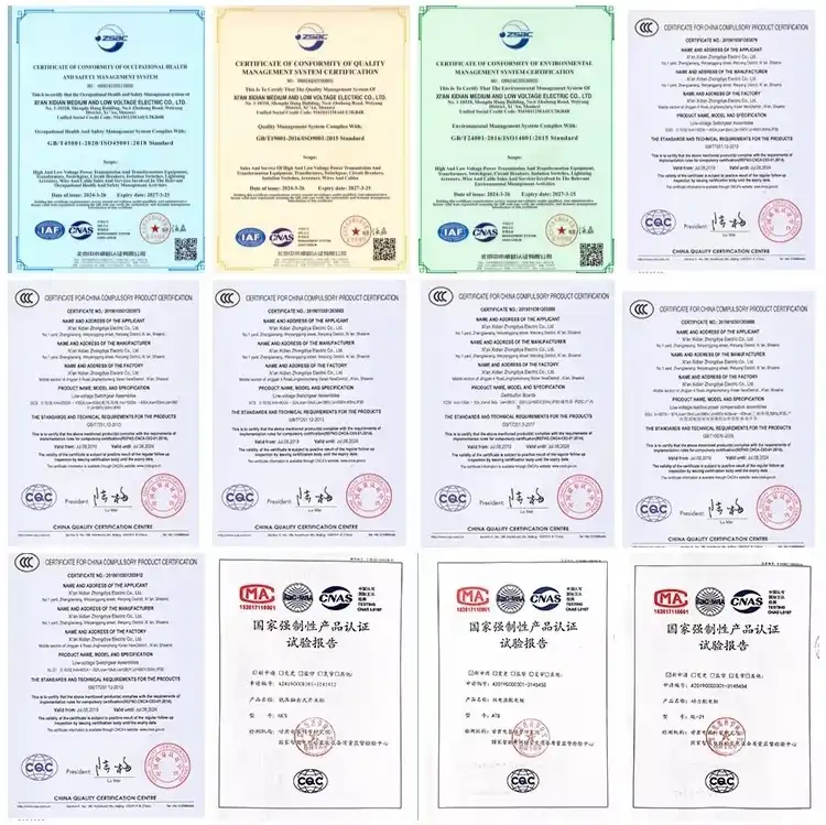
Before placing an order, check the technical datasheet from the seller to make sure of the following: the rated voltage and BIL; the kvar capacity per step and the total bank; the capacitor loss tangent (tan ε < 0.002); the vacuum switch durability (≥10,000 operations); the enclosure IP rating; and the ambient temperature range. Ask for type-test documents from a third-party facility that has been approved by the relevant authorities, citing IEC 60871 for capacitors and IEC 62271 for switchgear.
Evaluating Supplier Credibility and After-Sales Support
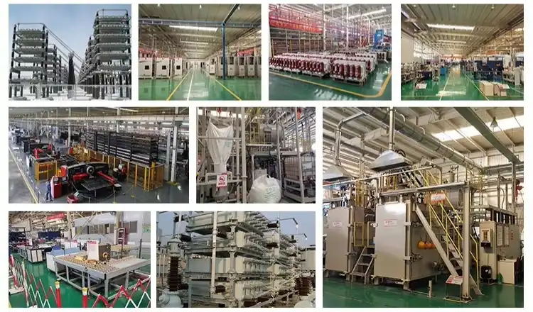
Over the past 30 years, Xi'an Xikai Medium & Low Voltage Electric Co., Ltd. has sold high-voltage equipment to utilities in over 40 countries. The company has 15 patents in the area of reactive power technology. Its outdoor reactive power compensation units can be bought through the State Grid ECP2.0 platform. To get this approval, the factory has to go through a lot of tests and audits. This is reassurance that county-level power companies and project managers for rural electrification can rely on when they put together annual batch bids for 50 to 300 units.
Understanding Lead Times and Order Planning
A normal lead time for a group of 50 to 100 pole-mounted compensation units is 8 to 12 weeks from the time the order is confirmed, which includes testing to make sure the units are ready for use. If the decision window for a yearly purchase cycle is two to four months, the technical specification and RFQ should be sent no later than the third quarter to make sure they are delivered before the next busy farming season. Make sure that the 10kV outdoor line compensation provider can offer extra vacuum switch modules and controller cards for at least 10 years after the delivery.
Troubleshooting and Maintaining 10kV Outdoor Line Compensation Systems
Common Field Faults and Diagnostics
Most of the time, pole-mounted compensation units have three problems: capacitor degradation (shown by rising tan µ during annual measurement), vacuum switch contact wear (confirmed by a contact resistance test greater than 50 μ©), and controller communication loss (caused by antenna damage or an expired SIM card on GPRS modules). A trained worker can tell the difference between each fault by looking at the field without taking the unit off the pole.
Routine Inspection Schedule
Even though these devices are made to work without any care in between yearly checks, it is still recommended that you do a visual check after every severe lightning event and a full electrical test once a year. As part of the yearly test, the capacitance should be measured (within ±5% of the label value), as well as the loss tangent, vacuum switch contact resistance, insulator cleaning, and proof that the sealing is complete according to the IP rating. Keep track of the unit's age over its 20-year service life by writing down results in a maintenance log.
When to Involve the Manufacturer
If the capacitance drifts more than 10% of its recommended value, if the controller keeps recording over-voltage events, or if the case shows signs of corrosion, you should contact the manufacturer's technical support team. Through its SCADA-linked tracking platform, Xi'an Xikai offers remote diagnostic help and can send field workers to places in China and partner countries when hardware needs to be replaced.
Conclusion
There is a set way to size 10kV outdoor line compensation outdoor reactive power compensation on 10kV distribution lines: you need to find the reactive deficit, choose the right bank size and placement, make sure the site has the right environmental protection, and check the technical credentials of the supplier. If you do each step correctly, the system will either reduce loss and improve voltage as promised, or it will become difficult to maintain. All of these needs can be met by Xi'an Xikai's modular outdoor line compensation equipment, which has arctic-rated shelters, an integrated PT power supply, and 4G remote tracking.
FAQ
Q1: How often does a pole-mounted compensation unit need maintenance?
Even though these units are made to work without any upkeep in the field, they still need to be inspected once a year to check the capacitance, vacuum switch contact resistance, and closing integrity. It is also best practice in the industry to do a visual check after big lightning events.
Q2: Can the system handle harmonic-rich grids?
Yes. The capacitor bank is structurally detuned against 5th and 7th order harmonics by built-in series reactors with 6% or 12% impedance. This stops resonance that could damage the capacitors or trip the protection relays.
Q3: How is the controller powered on a remote rural feeder?
An integrated potential transformer gets control power directly from the 10kV line, so it doesn't need a local LV supply. This is a design feature that solves the problem of power supply on long rural feeders.
Q4: What communication protocols are supported?
Modern units come with GPRS/4G modules that work with DNP3.0 and IEC 60870-5-104 protocols. This lets them fully integrate with SCADA and let the dispatch center send orders to the switches from afar.
Q5: What is the operating temperature range?
Standard units can work in temperatures ranging from -40°C to +55°C, which includes grid settings in tropical, desert, and high-altitude areas.
Get a Sizing Consultation from Xi'an Xikai — Your Trusted 10kV Outdoor Line Compensation Supplier
Xi'an Xikai has been designing outdoor reactive power compensation equipment for more than 30 years. This equipment is accepted on State Grid ECP2.0 and is used in remote electricity projects in China, Southeast Asia, and Africa. Our 10kV outdoor line compensation units are designed to work with tough outdoor grids. They have IP65 stainless steel enclosures, an integrated PT power supply, and 4G remote monitoring. Get in touch with our expert team right away to get a free size advice and quote on your order:
- Email: serina@xaxd-electric.com | amber@xaxd-electric.com | luna@xaxd-electric.com
- Website: xaxd-electric.com
References
1. IEC 60871-1: Shunt Capacitors for AC Power Systems Having a Rated Voltage Above 1 000 V — International Electrotechnical Commission, 2014.
2. IEC 62271-109: High-Voltage Switchgear and Controlgear — Alternating-Current Series Capacitor By-pass Switches — International Electrotechnical Commission, 2019.
3. IEEE Std 1036: IEEE Guide for Application of Shunt Power Capacitors — Institute of Electrical and Electronics Engineers, 2010.
4. State Grid Corporation of China: Technical Guidelines for Reactive Power Compensation on 10kV Distribution Networks — State Grid Corporation Research Report, 2022.
5. Wang, J. & Li, H.: Optimal Placement of Capacitor Banks in Rural Distribution Systems for Loss Reduction — IEEE Transactions on Power Delivery, 2020.
6. Grünbaum, R.: Reactive Power Compensation: A Practical Guide — John Wiley & Sons, 2017.