
mv capacitor bank
2.The capacitor bank allows continuous operation at a steady state overcurrent of 1.3 times the rated.
3. High Voltage Reactive Power Automatic Compensation Device Operation Instructions current due to overvoltage and higher harmonics.
4.The difference between the actual capacitance of the device and its rated capacitance shall not exceed (0~+10) % of the rated value, and the ratio of the maximum capacitance to the minimum capacitance between any two terminals of the device shall not exceed 1.06. ● The device can limit the inrush current generated by the capacitor bank instantaneously to less than 20 times the rated current of the capacitor bank.
- Fast Delievery
- Quality Assurance
- 24/7 Customer Service
Product Introduction
Medium Voltage Capacitor Bank - Advanced Power Factor Correction Solution
Product Introduction
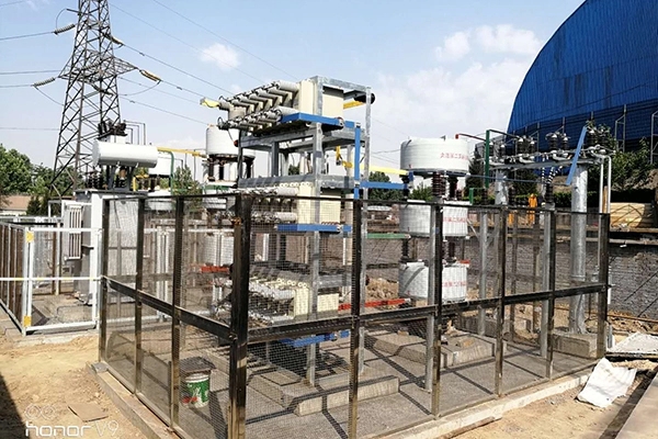
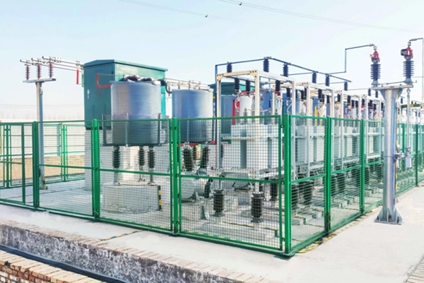
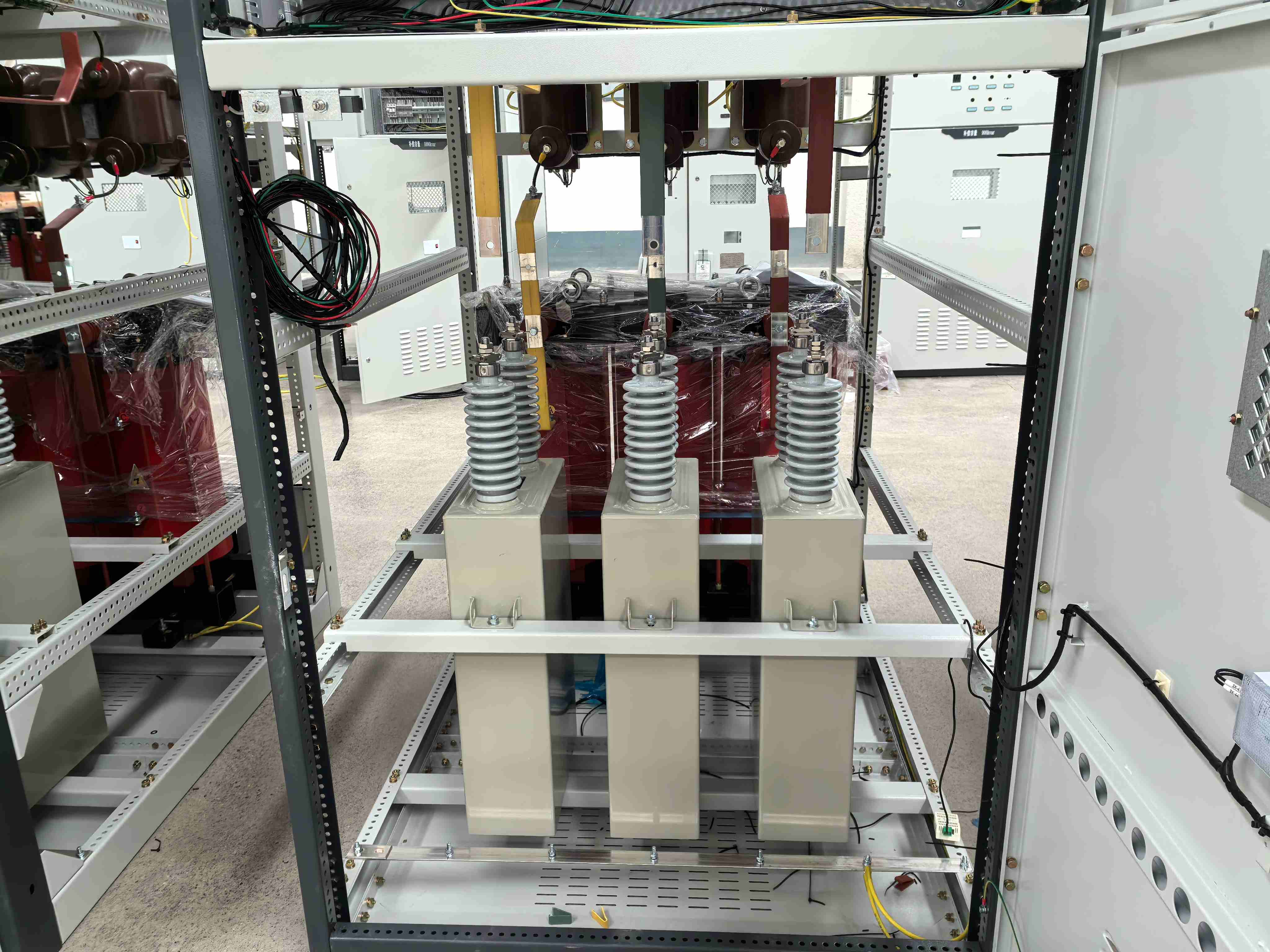
Looking to enhance your power system efficiency and reduce energy costs? Our mv capacitor bank delivers exceptional reactive power compensation for medium voltage networks ranging from 1kV to 36kV. This sophisticated electrical assembly combines multiple high-quality capacitor units in optimized series and parallel configurations to inject precise reactive power into your grid. Our mv capacitor bank effectively counteracts inductive loads from motors, transformers, and industrial machinery while eliminating costly utility penalties for poor power factor.
You'll experience immediate benefits including reduced current flow in cables and transformers, improved voltage stability, and significant reduction in technical losses throughout your distribution network. Each unit is engineered to operate continuously at 1.1 times rated voltage with peak harmonics up to 1.2√2Un, ensuring reliable performance in demanding industrial environments.
Technical Specifications
| Parameter | Specification |
|---|---|
| Voltage Range | 1kV - 36kV (up to 72.5kV special configurations) |
| Rated Current | 630A - 4000A |
| Continuous Overvoltage | 1.1 × Un (long-term operation) |
| Peak Voltage with Harmonics | ≤ 1.2√2Un |
| Steady State Overcurrent | 1.3 × In (continuous) |
| Capacitance Tolerance | 0 to +10% of rated value |
| Inrush Current Limitation | < 20 × rated current |
| Altitude Operation | Up to 4000m above sea level |
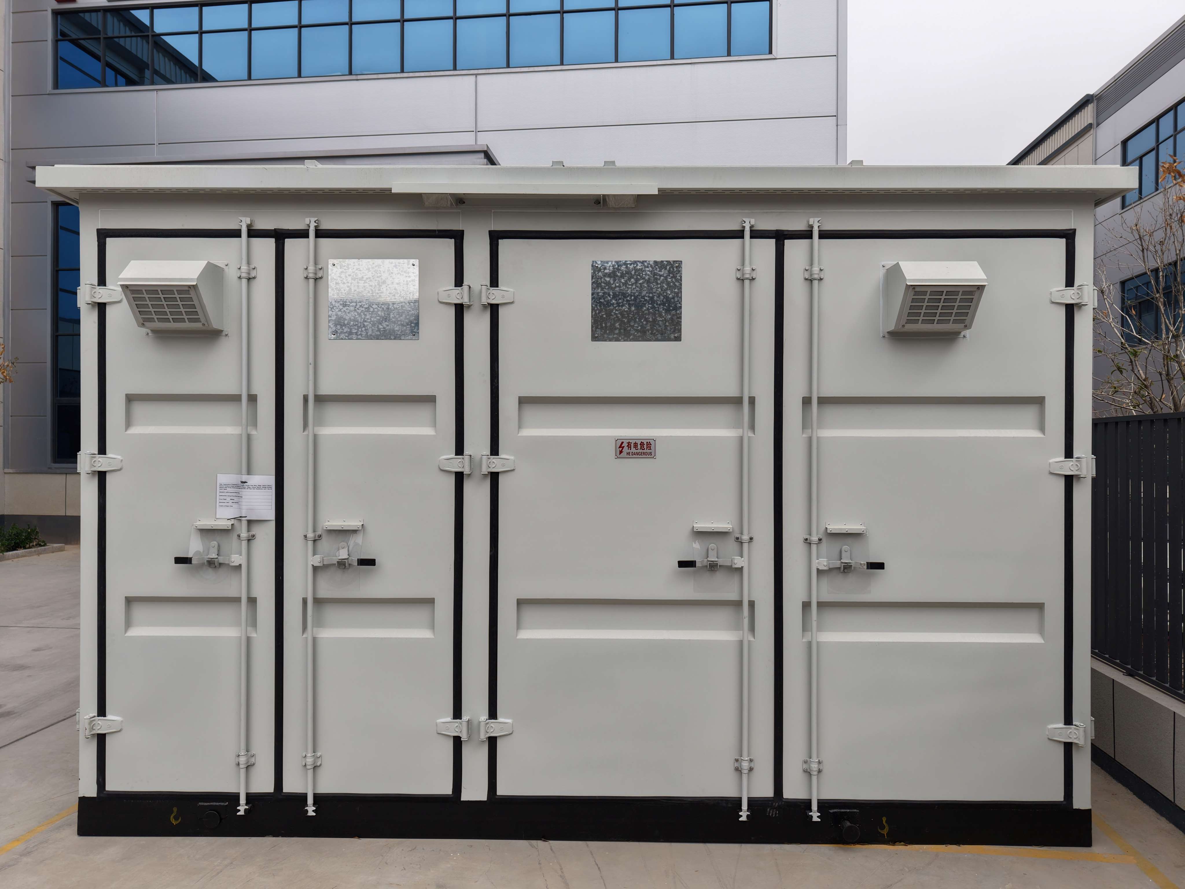
| Protection Class | IP54 / NEMA 3R (outdoor models) |
| Operating Temperature | -25°C to +40°C |
Main Features and Advantages
Superior Current Limitation Technology
Our advanced design incorporates inrush current limiting reactors that restrict instantaneous switching currents to less than 20 times the rated capacity, protecting your switchgear and extending equipment lifespan.
Precision Capacitance Control
Each unit maintains capacitance within 0-10% of rated values, with maximum variation between terminals under 1.06 ratio, ensuring consistent performance and predictable power factor correction.
Robust Overvoltage Handling
Built to withstand continuous operation at 110% rated voltage and temporary peaks up to 120% with harmonic content, providing exceptional reliability in unstable grid conditions.
Flexible Configuration Options
Available in both fixed and automatic switching configurations, our mv capacitor bank systems adapt to your specific load patterns and power factor requirements.
Practical Applications
Industrial Manufacturing
Perfect for steel mills, cement plants, and mining operations where large inductive loads demand robust reactive power support. Our enclosed designs handle dusty, high-vibration environments while paired with detuning reactors to prevent harmonic resonance.
Utility Distribution Networks
Grid operators rely on our open-rack configurations to maintain voltage profiles along transmission lines, featuring high-reliability fuseless designs that minimize maintenance interruptions.
Renewable Energy Integration
Wind and solar farms utilize our dynamic switching capabilities to meet strict grid code requirements at point of interconnection, managing rapid generation fluctuations effectively.
How It Works
Your mv capacitor bank operates by storing and releasing electrical energy in capacitive elements that generate leading reactive power. When inductive loads create lagging power factor, the capacitors automatically provide the necessary reactive power to achieve optimal power factor levels.
The system continuously monitors grid conditions through integrated protection relays. Automatic variants use vacuum contactors controlled by power factor controllers to step capacitance in or out based on real-time demand, preventing over-correction during light load periods.
Manufacturing Excellence
At Xi'an Xikai Medium And Low Voltage Electric Co.,Ltd., we maintain the highest manufacturing standards with ISO9001, ISO14001, and OHSAS18001 certifications. Our comprehensive product line spans 9 categories, 34 series, and over 100 varieties of power distribution equipment.
Every component undergoes rigorous testing to meet national and international standards. Our technical team ensures each mv capacitor bank delivers consistent performance across diverse operating conditions, from sea level to 4000m altitude installations.
Why Choose Us
Proven Industry Leadership
With decades of experience in medium voltage equipment, we understand the critical requirements of power factor correction in challenging industrial environments.
Comprehensive System Solutions
Beyond individual components, we provide complete system integration services, ensuring your reactive power compensation solution integrates seamlessly with existing infrastructure.
Advanced Engineering Support
Our technical specialists work closely with your team to design optimal configurations, considering harmonic content, load patterns, and future expansion requirements.
Quality Assurance
Every unit is manufactured to the highest standards and backed by comprehensive warranties, giving you confidence in long-term performance and reliability.
FAQ
Q: How do I prevent harmonic resonance with my new capacitor bank?
A: We recommend installing detuned reactors rated at 6%, 7%, or 13% in series with capacitors. This shifts resonance frequency below dominant grid harmonics, preventing amplification and protecting your investment.
Q: What's the expected lifespan of these units?
A: Under normal operating conditions with proper maintenance, our design life typically reaches 20 years. Regular annual inspections help ensure optimal performance throughout this period.
Q: Should I choose internal or external fusing?
A: For large installations, internal fuses offer superior availability. They isolate only faulty elements while allowing continued operation with minimal capacity loss, unlike external fuses that disconnect entire units.
Q: What maintenance is required?
A: Maintenance is minimal but essential. Annual visual inspections, connection torque verification, protection relay testing, and insulator cleaning ensure reliable long-term operation.
Contact Us
Ready to optimize your power system efficiency? Our technical specialists are standing by to discuss your reactive power compensation requirements and design the perfect solution for your application.
Email: serina@xaxd-electric.com
Contact us today for detailed specifications, custom configurations, and comprehensive system design support. Let our expertise help you achieve optimal power factor correction and significant energy cost savings.
Send Inquiry