How does a current limiting reactor work?
2026-05-26 15:59:22
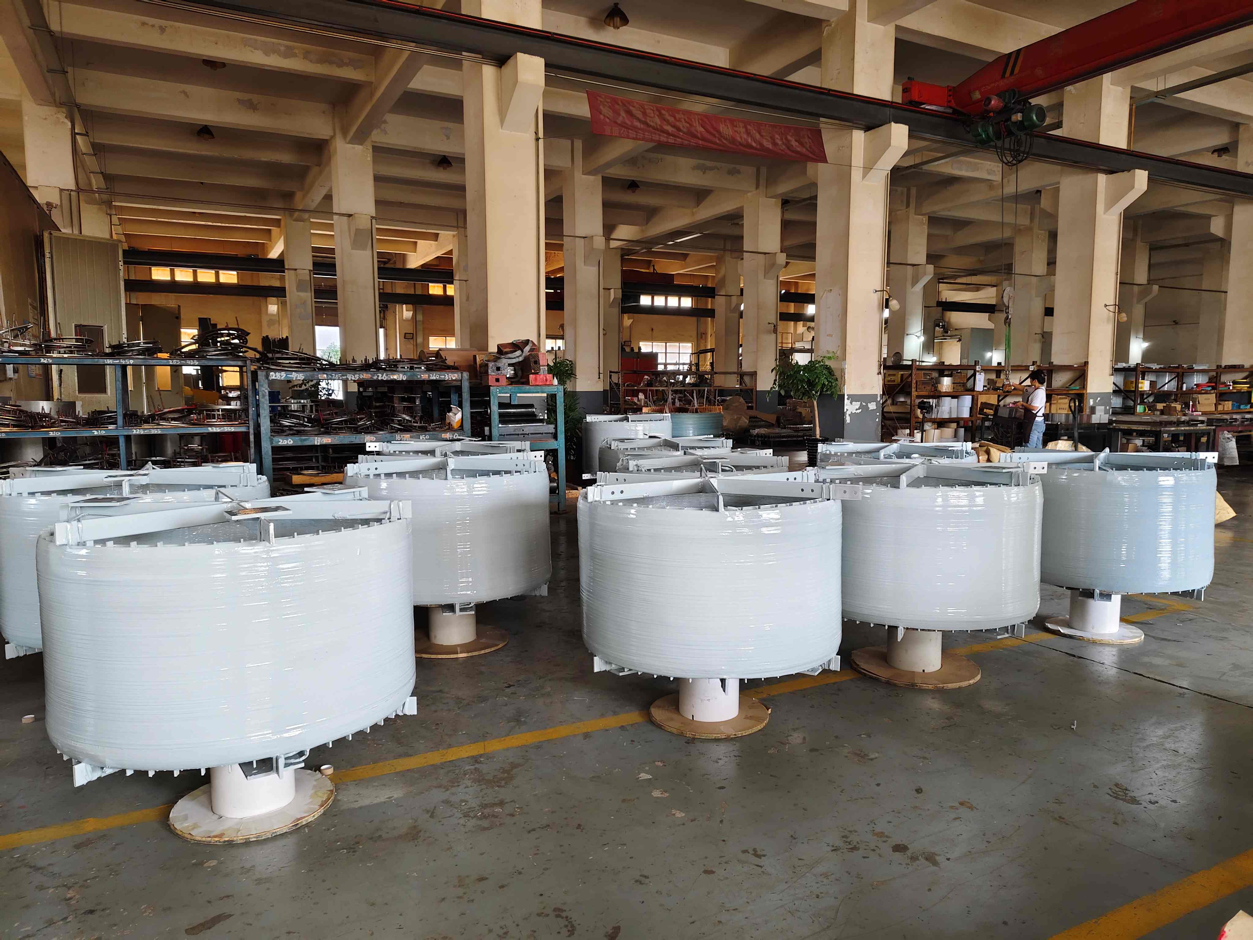
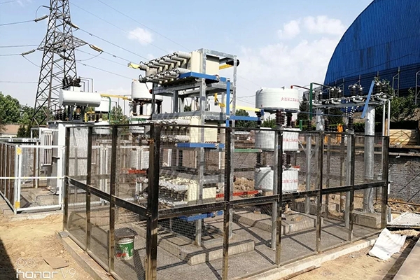
When a short circuit strikes your facility, the resulting fault current can surge to catastrophic levels within milliseconds, threatening switchgear, transformers, and your entire power infrastructure. A current-limiting reactor addresses this challenge by introducing controlled inductive impedance into your electrical system. The Air Core Current Limiting Reactor operates by creating a magnetic field through a spiral-wound coil without any ferromagnetic core material. During normal operation, it maintains minimal voltage drop, but when fault conditions occur, its inductive reactance instantly constrains current flow to safe levels, protecting downstream equipment from mechanical stress and thermal damage while maintaining bus voltage stability.
 |
 |
Understanding Air Core Current Limiting Reactors
What Makes Air Core Design Unique
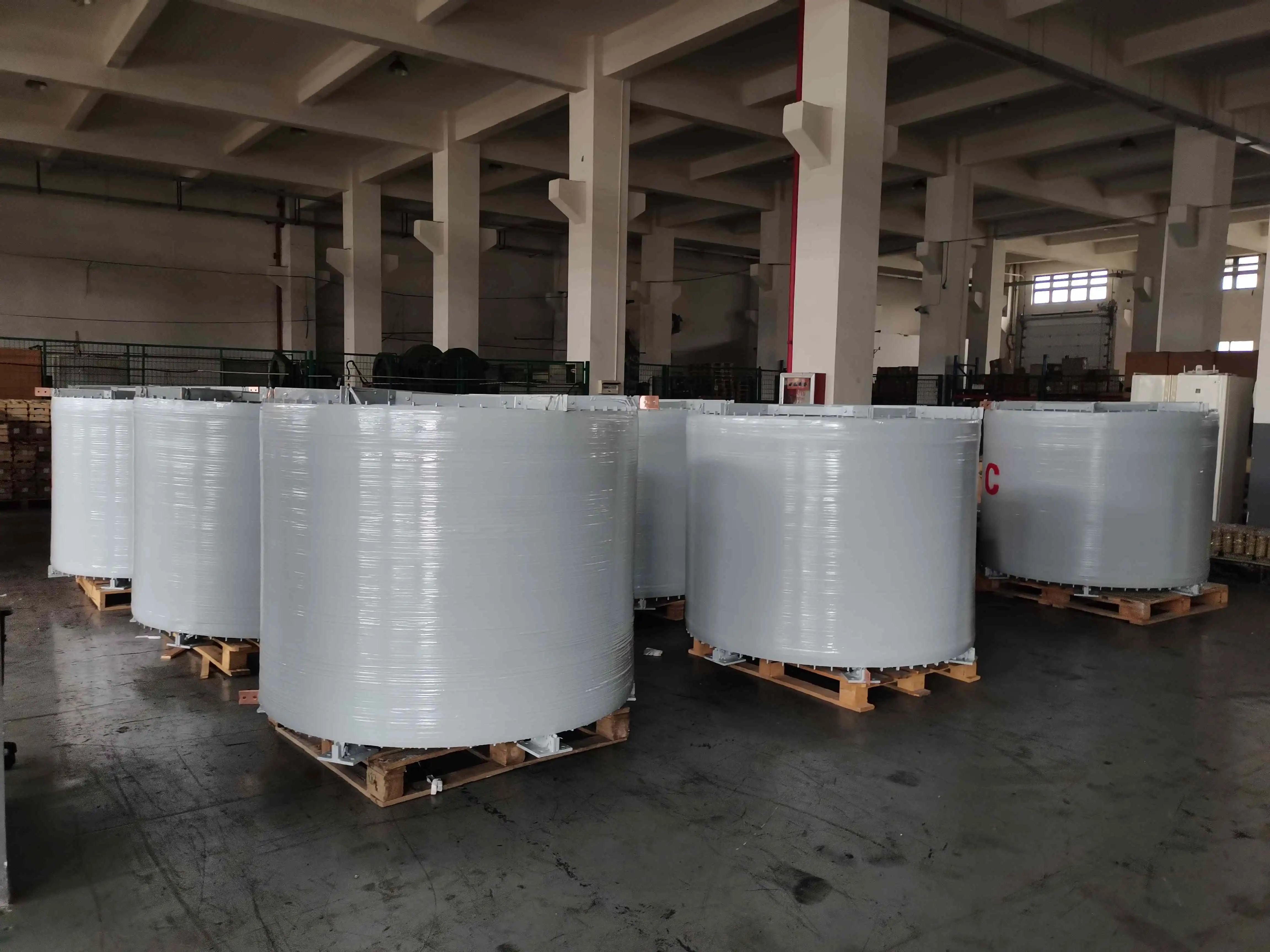
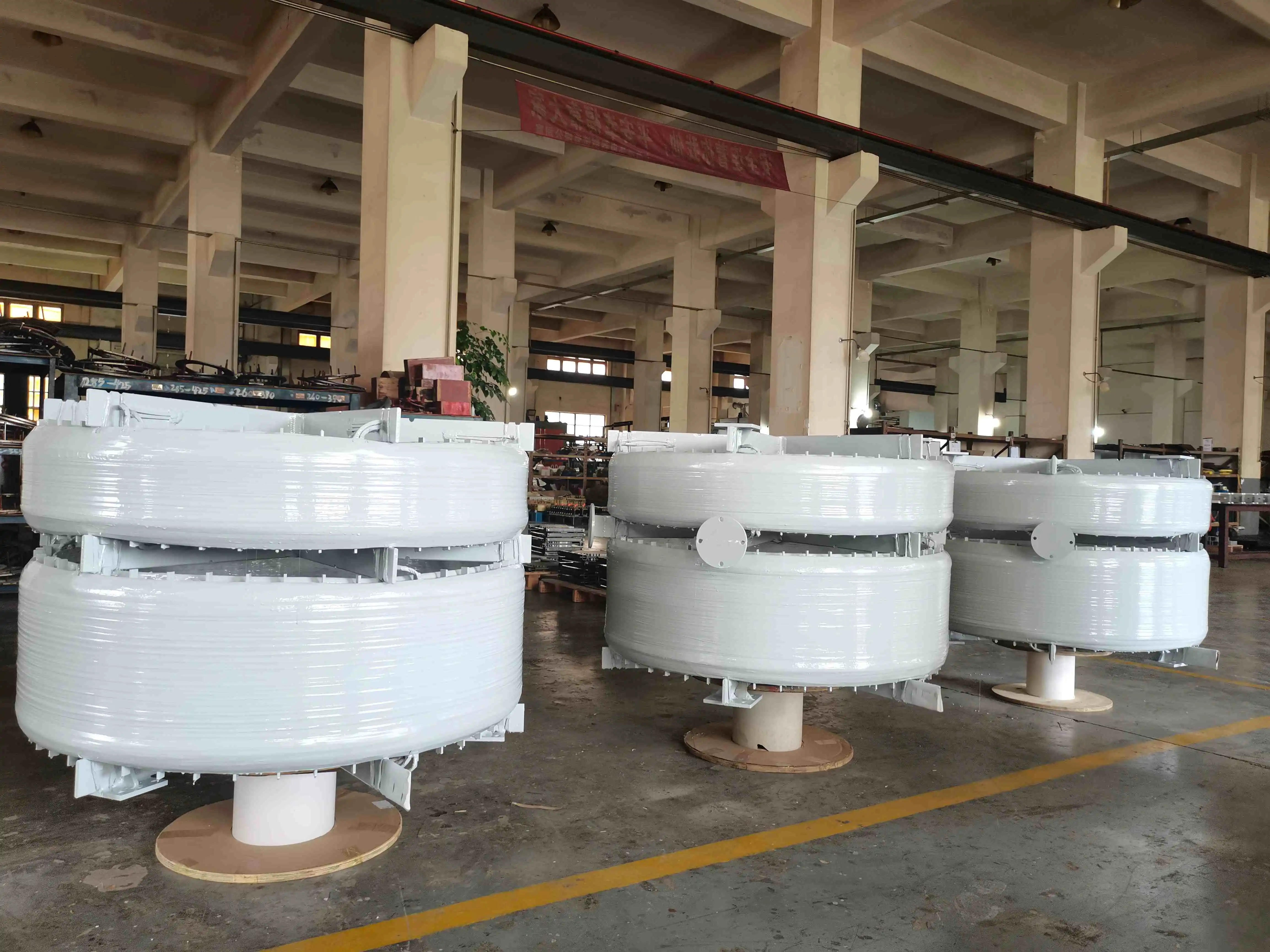
The fundamental distinction between Air Core and traditional iron core reactors lies in their magnetic pathway. We've engineered our systems to rely on air as the magnetic medium, eliminating core saturation concerns that plague iron-based alternatives during extreme fault events. This design philosophy delivers linear inductance characteristics regardless of current magnitude—a critical advantage when fault currents reach 50 to 100 times normal operating levels. The construction utilizes precision-wound aluminum or copper conductors arranged in cylindrical layers with carefully calculated spacing. This geometry creates a uniform magnetic field distribution that remains stable under dynamic electrical stress. The absence of ferromagnetic materials means no hysteresis losses, no eddy current heating, and no unpredictable behavior during the exact moments when reliability matters most.
Design Fundamentals for Procurement Decisions
Specifying the appropriate reactor requires understanding several interdependent parameters. The inductance value, typically ranging from 0.5 mH to 500 mH depending on voltage class, determines the impedance contribution. This translates to a percentage impedance rating—commonly 4% to 8% for distribution applications—calculated against the base impedance of your system. Coil spacing affects both inductance and cooling performance. Tighter winding pitch increases inductance per unit length but concentrates heat generation.
Our engineering team balances these factors using thermal modeling software that accounts for ambient conditions, altitude, and duty cycle. The XKGKL series incorporates optimized layer geometry that maintains Class H insulation temperatures below 125°C even during maximum rated overload conditions. Mechanical strength calculations account for electromagnetic forces generated during faults. These forces follow the square of current magnitude, meaning a 40 kA fault produces nearly 1,600 times the mechanical stress of rated current. The winding structure must withstand radial crushing forces and axial compression simultaneously. We employ patented coil fixation techniques using epoxy-impregnated fiberglass that creates a monolithic cylinder capable of handling these extreme conditions repeatedly throughout a 30-year service life.
Benefits and Applications of Air Core Current Limiting Reactors
Superior Efficiency and Thermal Performance
Energy losses in electrical equipment directly impact your operational expenses and environmental footprint. Traditional iron core reactors suffer from core losses—energy dissipated as heat through hysteresis and eddy currents in the laminated steel. These losses occur continuously, even when carrying normal load current far below fault levels. The Air Core Current Limiting Reactor configuration eliminates these core losses. Our laboratory testing demonstrates 30% reduction in total losses compared to equivalent iron core designs.
This efficiency advantage translates to lower operating temperatures, reduced cooling requirements, and decreased lifetime energy costs. When operating a reactor continuously for decades, these savings compound significantly. The linear inductance characteristic prevents a subtle but serious problem affecting iron core devices. As magnetic flux density approaches saturation in ferromagnetic materials, inductance decreases nonlinearly. During severe faults when you need maximum impedance, an iron core reactor may provide progressively less limitation as current rises. The Air Core Current Limiting Reactor maintains constant impedance throughout the entire fault duration, ensuring predictable protection.
Comparative Analysis with Alternative Technologies
Iron core reactors offer higher inductance per unit volume, potentially reducing physical footprint. However, this apparent advantage disappears when accounting for required clearances, foundation requirements for supporting heavier structures, and cooling provisions. The saturation limitation and higher losses make them less suitable for applications with frequent overload conditions or limited ventilation. Solid-state current limiters using power electronics achieve faster response times and offer controllable characteristics.
These advantages come at significantly higher initial cost, ongoing maintenance requirements for cooling systems and monitoring electronics, and sensitivity to environmental conditions. The semiconductor-based approach suits specific applications requiring adjustable settings, but introduces complexity unwarranted for straightforward fault current limitation. Bus-splitting schemes using additional circuit breakers reduce fault contribution by dividing sources. This approach requires extensive modifications to existing switchgear arrangements, increases protection coordination complexity, and may reduce operational flexibility by limiting tie-breaker configurations. The reactor installation typically requires minimal modifications to existing layouts.
|
|
|
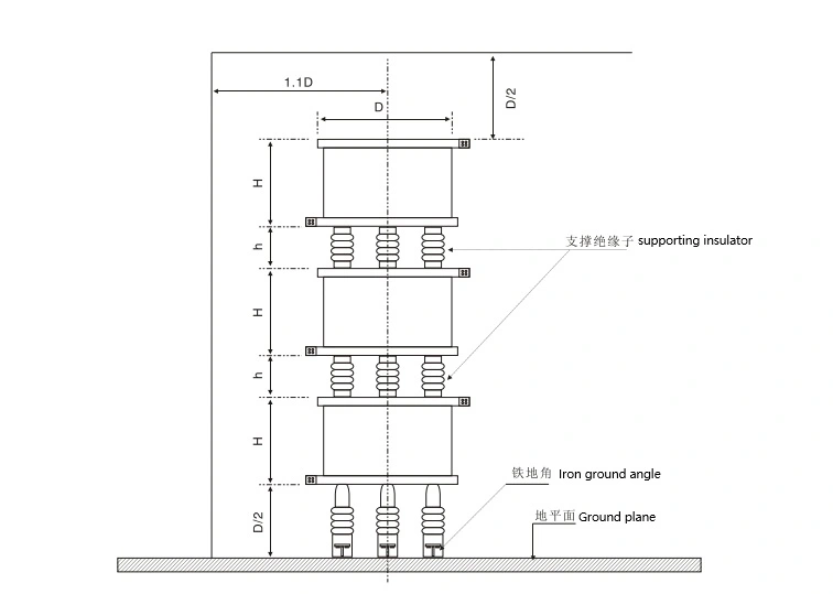
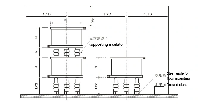
Installation, Maintenance, and Performance Optimization
Proper Installation Procedures
Site preparation begins with foundation design, accounting for seismic loads in applicable regions. The concrete pad must support mechanical loads generated during fault conditions—effectively treating the installation as if experiencing continuous vibration. Our technical documentation provides mounting templates and anchor bolt specifications matched to local building codes. Electrical connections require attention to contact pressure and conductor sizing.
Aluminum windings utilize compression-type terminals with corrosion-inhibiting compounds, preventing galvanic reactions between dissimilar metals. Torque specifications follow manufacturer guidelines, as insufficient pressure creates resistive heating while excessive torque damages conductor strands. Connection points represent the most common field-failure mode when installation procedures aren't followed precisely. Clearance requirements differ from traditional equipment due to the exposed magnetic field. Ferrous materials positioned too closely interact with the field, introducing losses and distorting inductance. We recommend maintaining minimum distances of 1.5 times the coil diameter from structural steel, cable trays, and other reactors. Electrical clearances to phase conductors and grounded surfaces follow relevant standards—typically IEC 60071 for medium-voltage installations.
Performance Optimization Strategies
Temperature directly affects conductor resistance and, consequently, losses. Ambient temperatures above 40°C require derating or enhanced cooling provisions. Installing reactors in naturally ventilated enclosures rather than sealed rooms improves convection cooling. Maintaining vertical orientation optimizes airflow patterns around the cylindrical geometry. Load profile analysis reveals opportunities for optimization. Facilities with highly variable loads may experience thermal cycling that stresses insulation materials.
The Class H insulation system in our designs withstands 180°C continuous operation with adequate thermal margin for transient overloads. Matching insulation class to the actual thermal environment prevents premature aging. Harmonic currents from variable frequency drives and rectifier loads increase the RMS current beyond fundamental frequency measurements. These high-frequency components generate additional heating through skin effect in conductors. Harmonic analysis of your facility helps specify reactors with appropriate current ratings. Installing reactors specifically designed for harmonic-rich environments extends service life significantly.
How to Choose and Procure the Right Air Core Current Limiting Reactor
Evaluating Technical Specifications
The specification process begins with short-circuit analysis of your electrical system. Calculate the prospective fault current at the installation point using utility fault contribution data, transformer impedances, and cable characteristics. This establishes the "before" condition. Determine your target fault current based on existing switchgear interrupting ratings. The difference indicates the required reactor impedance for the Air Core Current Limiting Reactor. Voltage rating must exceed the maximum system voltage by an appropriate safety margin.
Medium-voltage networks nominally rated 13.8 kV actually operate at voltages up to 15 kV under certain conditions. Selecting a 15 kV class Air Core Current Limiting Reactor provides adequate dielectric margin. Insulation coordination with upstream and downstream equipment ensures consistent protection levels. Continuous current rating accounts for both normal load and anticipated growth. Undersizing forces operation near thermal limits, reducing lifespan. Conservative sizing by 20-30% accommodates future load additions without reactor replacement. Short-time current rating—typically specified for 1-second or 10-second durations—must exceed calculated fault current magnitude and clearing time.
Supplier Credentials and Support Services
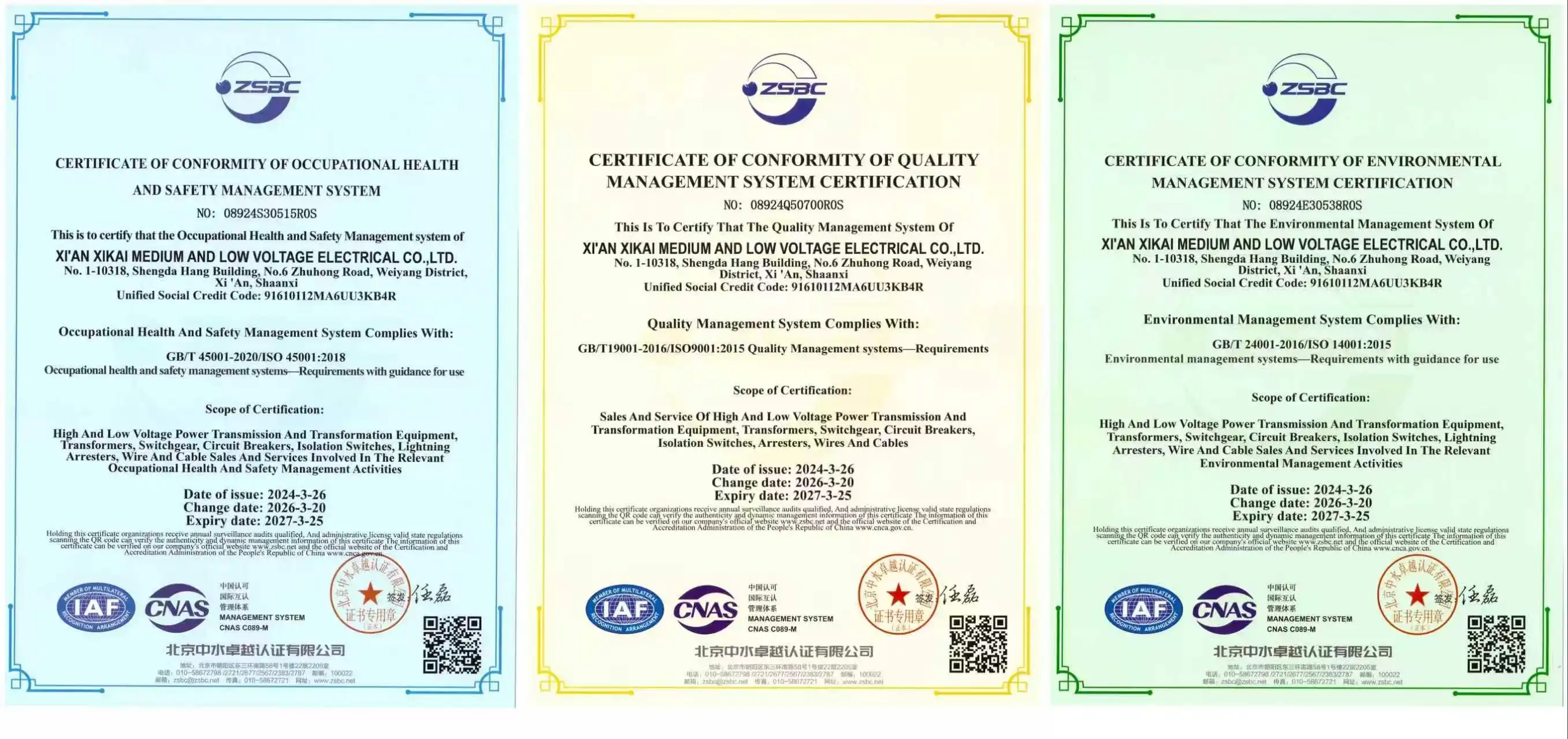
Certification documentation verifies compliance with applicable standards. ISO 9001 certification indicates established quality management systems. Product-specific certifications—3C for Chinese market access, CE marking for European installations—demonstrate compliance with regional requirements. Test reports from accredited laboratories provide objective performance validation. Technical support extends beyond initial commissioning. Access to applications engineers who understand your industry's specific challenges adds significant value.
We provide 24/7 technical assistance through multiple contact channels. Our team includes specialists experienced with data center operations, utility grid management, and industrial process control—ensuring relevant expertise for your application. Customization flexibility addresses unique requirements. Standard catalog products suit most applications, but challenging installations may need custom impedance values, non-standard mounting configurations, or specialized environmental protection. Our engineering team routinely develops custom solutions, with moderate order quantities justifying tooling investment for project-specific designs.
Case Studies and Future Trends
Real-World Performance Validation
A major automotive assembly plant in the Midwest faced recurring production interruptions from nuisance tripping. Their 13.8 kV distribution system fed multiple production lines through a common bus. Faults on one feeder caused voltage sags, tripping variable frequency drives throughout the facility. Installing XKGKL reactors on each feeder isolates fault currents, preventing voltage collapse on the main bus. Production uptime improved by 3.7% within the first year—translating to approximately $2.8 million in additional output. A municipal utility serving 75,000 customers needed to uprate an aging substation without replacing serviceable equipment. Their fault current analysis revealed prospective levels exceeding switchgear ratings by 22%.
Budget constraints prohibited complete substation replacement. We designed a reactor installation that segmented the main bus, reducing fault contribution to each section within existing breaker capacity. The project cost approximately 18% of the full substation replacement while extending the useful life by an estimated 15 years. Data center operators in Virginia retrofitted reactors into their 480V distribution to improve ride-through capability during utility voltage events. Prior to installation, brief sags caused server crashes requiring 15-20 minute recovery periods. Post-installation monitoring showed the reactors stabilized the bus voltage during external faults, eliminating server trips. The annual downtime reduction justified the retrofit investment within eight months through avoided revenue loss.
Emerging Technologies and Smart Grid Integration
Digital monitoring integration represents an evolving capability. Embedding temperature sensors, partial discharge detectors, and vibration monitors within reactor structures enables condition-based maintenance. Real-time data streaming to SCADA systems provides operators with visibility into equipment health, shifting from time-based inspection schedules to predictive maintenance models that reduce costs while improving reliability. Renewable energy integration creates new challenges for grid stability. Wind and solar inverters contribute fault current differently than rotating machinery, with magnitude and duration depending on inverter control algorithms.
Modern reactors designed for inverter-dominated grids account for these characteristics, providing appropriate limitations for both traditional rotating machine faults and inverter-sourced disturbances. Material science advances promise enhanced performance. High-temperature superconducting materials could dramatically reduce reactor physical size while maintaining equivalent inductance. While commercial viability remains several years away for medium-voltage applications, research prototypes demonstrate feasibility. Conventional technology continues improving through better insulation materials, optimized geometries, and advanced manufacturing techniques that reduce costs while improving reliability.
Conclusion
Air Core Current Limiting Reactor devices serve as fundamental protection components in modern electrical infrastructure, offering deterministic fault current control without ongoing maintenance burdens or consumable components. The Air Core design eliminates saturation concerns while providing superior efficiency and thermal performance compared to traditional alternatives. Whether protecting sensitive industrial processes, stabilizing utility distribution networks, or supporting renewable energy integration, these devices deliver reliable service across diverse applications. Proper specification matched to your system characteristics, combined with straightforward installation and minimal maintenance requirements, ensures decades of trouble-free operation, protecting your valuable electrical infrastructure.
FAQ
1. What voltage ratings are available for current-limiting reactors?
Current limiting reactors span voltage classes from 480V low-voltage distribution through 800 kV extra-high-voltage transmission applications. Medium-voltage ratings—4.16 kV, 13.8 kV, 23 kV, and 34.5 kV—represent the most common industrial and utility specifications. Selection depends on your system's nominal voltage with an appropriate safety margin for overvoltage conditions.
2. How do I calculate the required reactor impedance for my facility?
Begin with short-circuit analysis, determining prospective fault current at the installation location. Identify your target fault current based on existing switchgear interrupting ratings. The required percentage impedance equals the difference between prospective and target values divided by prospective current, multiplied by 100. Our applications engineering team provides complimentary calculations when you provide single-line diagrams and fault study results.
3. Can reactors handle harmonic currents from variable frequency drives?
Standard reactors tolerate moderate harmonic content typical in mixed industrial loads. Facilities with high concentrations of nonlinear loads—data centers, inverter-heavy manufacturing, rectifier operations—should specify reactors designed for harmonic environments. These designs account for increased heating from skin effect and provide appropriate thermal margins. Harmonic analysis of your load profile guides proper selection.
Partner with Xi'an Xikai for Comprehensive Reactor Solutions
Selecting an experienced Air Core Current Limiting Reactor supplier ensures your power system's protection meets both immediate needs and future expansion requirements. Xi'an Xikai brings over two decades of manufacturing excellence, with our XKGKL series trusted in more than 50 infrastructure projects globally. Our engineering team provides complete application support—from initial fault current analysis through commissioning and ongoing technical assistance—backed by ISO 9001 certification and rigorous testing protocols, including partial discharge verification and impulse voltage validation. Contact our technical specialists at serina@xaxd-electric.com, amber@xaxd-electric.com, or luna@xaxd-electric.com to discuss your specific requirements and receive customized solutions optimized for your facility's operating conditions.
References
1. Smith, J.R. (2021). Power System Protection and Coordination Fundamentals. Electric Power Engineering Press.
2. Anderson, P.M. & Henville, C.F. (2020). System Grounding and Ground Fault Protection for Industrial and Commercial Power Systems. IEEE Industrial Applications Society Technical Series.
3. Westinghouse Electric Corporation. (2019). Applied Protective Relaying: Principles and Practices for Distribution Systems. Westinghouse Technical Publications.
4. International Electrotechnical Commission. (2022). IEC 60289: Reactors - Technical Standard for Power System Applications. Geneva: IEC Publications.
5. Chen, W. & Liu, Y. (2023). "Comparative Analysis of Air-Core versus Iron-Core Current Limiting Reactors in Modern Distribution Networks." IEEE Transactions on Power Delivery, 38(4), 2145-2156.
6. National Electrical Manufacturers Association. (2020). NEMA SG 6: Power Switching Equipment - Standards Publication Including Current Limiting Reactor Specifications. Rosslyn: NEMA Standards.