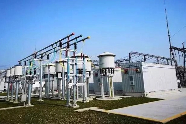
What Is a Line Current Limiting Reactor and How Does It Work?
2026-08-27 15:10:41
A line current limiting reactor is a specialized series-connected inductive device engineered to control and reduce short-circuit currents in power transmission and distribution networks. When a fault occurs, this reactor increases system impedance, effectively lowering the fault current to safe levels that existing switchgear can handle. The operating principle relies on electromagnetic induction: the reactor's coil generates an opposing magnetic field during fault conditions, creating impedance that restricts current flow. This protection mechanism prevents equipment damage, maintains grid stability, and eliminates the need for costly circuit breaker replacements during network expansion.


Understanding Line Current Limiting Reactors
Fundamental Operating Principles
Modern electrical grids face growing fault current challenges as generation sources multiply and networks spread. At the heart of problem current control lies electromagnetic theory. When current flows through a line current limiting reactor's winding, it creates a magnetic field that opposes sudden changes in current magnitude. During normal operation, the line current limiting reactor presents minimal impedance—typically 0.1% to 14% depending on application. However, when a short circuit occurs, the instantaneous current surge induces a powerful counter-electromotive force that effectively "pushes back" against the fault current, limiting it to permissible values that protect downstream equipment.
The physics behind this protection is elegant: according to Lenz's Law, the induced voltage across the line current limiting reactor coil opposes the change causing it. This self-regulating characteristic makes line current limiting reactors passive yet reliable guardians of power system integrity, requiring no active control systems or decision logic to perform their protective function.
Key Electrical Characteristics
Understanding the electrical parameters of these devices proves essential for proper system integration. Inductance, measured in millihenries (mH), determines how much impedance the line current limiting reactor introduces. Rated current defines the continuous thermal capability, while short-time current withstand capacity—often 50 kA or higher for transmission applications—indicates the line current limiting reactor's ability to survive fault events without mechanical failure.
Resistance represents power losses during operation, making it a critical efficiency metric. Quality factor (Q-factor) expresses the ratio of inductive reactance to resistance; higher Q-factors indicate lower energy waste. Basic Impulse Level (BIL) defines the line current limiting reactor's insulation strength against lightning and switching surges, typically ranging from 75 kV to 1,550 kV depending on system voltage class.
Types of Current Limiting Reactors
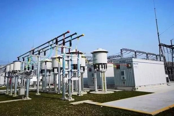
Three primary construction types serve different application needs. Air-core line current limiting reactors utilize non-magnetic support structures, offering completely linear inductance characteristics regardless of current magnitude. This linearity prevents magnetic saturation during extreme fault conditions, making air-core designs ideal for high-voltage transmission systems where predictable performance is paramount.
Iron-core line current limiting reactors incorporate ferromagnetic materials to achieve higher inductance in more compact physical dimensions. The magnetic core concentrates flux, enabling smaller footprints and lower costs. However, iron cores can saturate under extreme fault currents, potentially reducing effectiveness when protection is most needed.
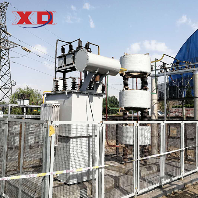
Dry-type line current limiting reactors use air or resin wrapping for insulation rather than oil, removing fire dangers and environmental contamination risks. The XKGKL series demonstrates this method, combining air-core linearity with dry-type safety. These units feature epoxy-impregnated fiberglass encapsulation that withstands electrodynamic forces exceeding 50 kA while maintaining Class H thermal performance up to 180°C. Their construction eliminates iron losses entirely, achieving 30% better energy efficiency compared to traditional designs—a significant advantage in continuous-duty applications where even small losses compound over years of operation.
Core Applications and Benefits in Power Systems
Recognizing where and why to put line current limiting reactors helps engineers build more reliable infrastructure. Three primary sectors demonstrate their indispensable value.
Grid Expansion and Substation Retrofitting
Utilities face a recurring challenge: as they parallel transformers or integrate new generation sources, fault current levels rise. Replacing functional circuit breakers solely because fault duties have increased represents enormous capital expenditure. Installing a line current limiting reactor in series with bus-ties or main feeders raises system impedance intelligently, lowering potential fault currents to levels existing switchgear can stop safely.
This approach proves particularly valuable in urban substations where physical space constraints prevent equipment upgrades. The line current limiting reactor enables grid reinforcement without costly infrastructure replacement, extending the service life of existing assets while maintaining safety margins required by IEEE and IEC standards.
Heavy Industrial Power Systems
Energy-intensive industries operating arc furnaces, large motor drives, and variable frequency drives generate substantial inrush currents during equipment startup. These transient surges stress distribution equipment and create voltage notches that compromise power quality for sensitive production processes.
Steel mills and petrochemical plants employ line current limiting reactors to smooth these transients, protecting both the industrial loads and utility supply infrastructure. When a 15 MW arc furnace strikes, the line current limiting reactor limits the initial current rush that would otherwise cause voltage flicker affecting neighboring processes. Similarly, when large pump motors start, the line current limiting reactor dampens the inrush to 5-7 times rated current rather than 10-12 times, reducing mechanical stress on motor windings and extending equipment lifespan.
Renewable Energy Integration
At the point where wind farms and solar arrays connect to utility grids, they each bring their own set of problems. Due to the way inverters work, large-scale renewable installations can cause large fault currents that may be higher than what is allowed by grid codes. Installed line current limiting reactors at the PCC handle this fault contribution while reducing switching transients caused by the inverter's operation.
Also, these line current limiting reactors help renewable energy sources follow strict rules for harmonic distortion and fault ride-through. By precisely controlling impedance between the generation source and grid, they enable clean energy integration without compromising system stability or power quality.
The tangible benefits across these applications include enhanced equipment longevity through reduced electrical stress, minimized operational downtime by preventing cascading failures, substantial cost avoidance by eliminating premature equipment replacement, and improved power quality that supports modern digital loads and precision manufacturing.
Technical Specifications and Design Considerations
Sizing and Selection Guidelines
Proper line current limiting reactor selection begins with comprehensive system analysis. Engineers must quantify maximum prospective fault current at the installation point, determine the existing interrupting capacity of circuit breakers, and calculate the impedance needed to limit fault current to acceptable levels.
The sizing equation is straightforward: needed impedance equals the difference between probable fault current and wanted limited current, divided by system voltage. In real life, tho, you have to take into account things like system X/R ratios, DC offset factors, and asymmetrical current peaks that can change how well the breaker works.
IEC 60076-6 and IEEE C57.16 standards provide methods for finding these factors while ensuring thermal and mechanical integrity. Engineers should check that the chosen line current limiting reactor can withstand the electrodynamic forces created during through-fault conditions—forces that can reach hundreds of tons in high-current applications.
Critical Design Elements
Core material selection dramatically affects performance characteristics. Air-core designs using fiberglass or polymer supports maintain constant inductance regardless of current magnitude, preventing saturation-related protection failures. The XKGKL series employs spiral-wound aluminum conductors configured in helical arrangements that minimize stray magnetic fields while maximizing mechanical strength.
The configuration of the coil winding affects both its electrical performance and its size. Multi-layer windings achieve higher inductance values but require careful inter-turn insulation to withstand impulse voltages. Winding tension during manufacturing proves critical—insufficient tension allows conductor movement during fault conditions, causing insulation abrasion and eventual failure.
Thermal management determines continuous rating and overload capability. Class F insulation (155°C) suffices for mild conditions, while Class H (180°C) allows operation in extreme settings where ambient temperatures reach 55°C. The XKGKL design incorporates enhanced cooling channels that dissipate heat efficiently even under sustained overload, preventing hotspot formation that degrades insulation over time.
Noise considerations matter particularly for installations near occupied buildings. Magnetostriction in iron-core designs generates audible hum, sometimes exceeding 85 dB at one meter. Air-core line current limiting reactors produce significantly lower acoustic emissions—typically below 45 dB—making them suitable for urban substations and commercial facilities where noise ordinances apply.
Maintenance and Installation Best Practices
Unlike oil-filled equipment requiring regular sampling and testing, dry-type air-core line current limiting reactors demand minimal maintenance. Visual checks are done once a year to make sure that the support structures are still in good shape and that the winding surfaces haven't become dirty. Thermal imaging identifies hotspots indicating connection issues before they cause failures.
Installation location affects long-term reliability. Adequate clearance around the line current limiting reactor ensures proper ventilation and allows magnetic fields to dissipate safely. Engineers should maintain minimum separation distances specified by the manufacturer—typically 1.5 to 3 meters from adjacent equipment—to prevent magnetic coupling that could induce unwanted voltages or heating in nearby conductors.
Seismic considerations prove essential in earthquake-prone regions. With the right foundation design and flexible connections, ground motion can be handled without damaging the line current limiting reactor structure. The XKGKL series offers seismic-rated configurations meeting UBC Zone 4 requirements, suitable for high-risk geographical areas.
Choosing the Right Current Limiting Solution
Reactors Versus Other Protective Devices
Line current limiting reactors serve a distinct function from circuit breakers and fuses, though they work synergistically within protection schemes. Fuses and breakers interrupt fault currents after detecting them, effectively isolating faulted sections. Line current limiting reactors prevent excessive fault currents from developing, protecting the interrupting devices themselves.
This complementary relationship proves vital in modern systems. A line current limiting reactor reduces the fault current magnitude, allowing smaller, less expensive circuit breakers to provide security. The breaker still performs its stoppage function, but under far less stressful conditions that stretch its service life and improve reliability.
Line current limiting reactors also maintain system continuity during faults. Unlike breakers that remove circuits from service, line current limiting reactors stay in operation, allowing unfaulted parts of the network to continue working. This selectivity reduces the scope of outages and improves overall system availability.
Air-Core Versus Iron-Core Comparison
Choosing between these technologies involves balancing multiple factors. Air-core line current limiting reactors deliver superior linearity, maintaining constant impedance from zero current through maximum fault levels. This predictability ensures protection remains effective under all operating conditions. Their lighter weight simplifies installation and reduces structural requirements, while elimination of iron losses improves efficiency by up to 30%.
Iron-core line current limiting reactors achieve higher inductance per unit volume, enabling more compact installations where space is constrained. Projects that want to stick to a budget will like their lower starting cost. However, potential saturation during extreme faults can compromise protection effectiveness precisely when it matters most.
Energy efficiency calculations over the line current limiting reactor's 30-year service life often favor air-core designs despite higher upfront costs. A 1000 kVA line current limiting reactor running constantly at rated current with just 2% lower losses saves tens of thousands in energy costs over its lifetime, covering the original price premium while lowering carbon footprint.
Industry Benchmarks and Supplier Landscape
Leading makers including Siemens, ABB, and Schneider Electric offer complete line current limiting reactor portfolios covering voltage classes from 480V to 765 kV. These established brands provide proven designs backed by extensive type testing and global installation experience.
Xi'an Xikai has emerged as a competitive alternative, particularly for customized applications requiring adaptation to specific site conditions. Our engineering team collaborates with clients to tailor impedance values, configure enclosures for harsh environments, and integrate monitoring systems that enable predictive maintenance. Projects across State Grid sites and Belt and Road infrastructure projects show our potential to deliver effective solutions meeting international standards.
Product selection should consider not just initial specifications but total lifecycle value. Warranty terms, spare parts availability, technical support responsiveness, and manufacturer financial stability all influence long-term project success. Established suppliers demonstrate their commitment through comprehensive documentation, accessible application engineering, and field service capabilities that resolve issues quickly when they arise.
Procurement Insights for B2B Buyers
Comprehensive Buying Criteria
EPC companies and design schools assessing line current limiting reactor suppliers should employ a structured assessment framework. Technical capability testing starts with reviewing type test results showing agreement with IEC 60076-6 and IEEE C57.16 standards. Look for documented evidence of short-time current withstand testing at rated fault levels—this empirical validation proves the line current limiting reactor can survive actual fault events without mechanical deformation or insulation failure.
Manufacturing quality systems certified to ISO 9001 and ISO 14001 indicate consistent production processes and environmental responsibility. For projects in specific areas, regional certificates matter: 3C certification for China, UL listing for North America, CE marking for Europe.
Delivery timelines significantly impact project schedules. Standard designs typically ship within 8-12 weeks, while customized units require 16-24 weeks for engineering, manufacturing, and testing. Clear up lead times early on in the buying process to avoid delays in the key path. Payment terms and pricing transparency build confidence—reputable suppliers provide detailed quotations itemizing base unit costs, optional features, shipping, and commissioning support.
Customization that can be changed easily is helpful for projects that have specific needs. Can the provider change the resistance values to fit certain fault studies? Do they have different housing grades for harsh environments or environments that rust? Suppliers who work with clients to create custom solutions are different from those who only sell stock items.
After-Sales Support and Technical Partnership
Technical consultation during design phases adds substantial value beyond product supply. Manufacturers with a lot of experience can help with system studies, suggest the best ways to install things, and find problems before the equipment ships. This proactive involvement avoids expensive field modifications and commissioning delays.
Commissioning help ensures safe installation and startup. Factory technicians should be ready to monitor initial energization, check electrical parameters, and teach facility staff on operation and maintenance procedures. Comprehensive documentation including installation drawings, test certificates, and maintenance manuals supports ongoing asset management.
Warranty coverage reflects manufacturer confidence in product quality. Standard terms usually cover manufacturing flaws for two years, but the best suppliers cover them for five years or longer. Make sure you understand what the guarantee covers. Some warranties don't cover damage caused by system errors or bad installation, while others cover all possible failures.
Line current limiting reactors can be used for their full 30-year design life as long as parts are available for a long time. Suppliers should promise to keep spare parts for important parts like terminals and support insulators in stock. As a major manufacturing base for medium and low-voltage electrical equipment, Xi'an Xikai keeps extensive inventory supporting fast parts delivery, reducing downtime if service becomes necessary.

Conclusion
Line current limiting reactors are a beautiful way to handle the growing problem of managing fault currents in power systems that are growing. These passive devices protect valuable assets, extend the life of equipment, and allow networks to grow without having to pay a lot of money to replace infrastructure. They do this by raising system impedance during faults. The XKGKL series and other air-core designs offer better performance thanks to their linear impedance characteristics, high energy efficiency, and strong construction that can last for decades of continuous use in harsh environments. Successful rollout requires careful attention to system analysis, proper sizing, and selection of qualified providers who provide not just products but expert partnership throughout project lifecycles. Line current limiting reactors will continue to be important for keeping electrical infrastructure safe and stable as power systems change to include more green energy and update the grid.
FAQ
1.What distinguishes current limiting reactors from surge reactors?
Line current limiting reactors are forever connected in series with power circuits. When short circuits happen, they stop fault currents from flowing. On the other hand, surge reactors protect against short-term overvoltages caused by lightning or switching operations. Even tho both work on inductive principles, they are rated and used in very different ways. Line current limiting reactors focus on temperature and mechanical withstand during extended problems, while surge reactors focus on impulse voltage withstand capability.
2.How often do current limiting reactors require maintenance?
Compared to equipment that is filled with oil, dry-type air-core line current limiting reactors require less upkeep. Visual inspections once a year are enough to make sure that most installations are still in good shape and are clean. Every two to three years, infrared thermography finds link problems that are starting to show up. Every 5 to 10 years, or when something goes wrong with the system, a full test is usually done that includes measuring the insulation resistance and inductance. This feature of low maintenance cuts down on lifecycle costs by a large amount.
3.Can reactors retrofit into existing electrical systems?
With the right tech, retrofitting is completely possible. The line current limiting reactor is connected in series with the circuit that needs to be protected, which is usually between the bus and the feeder breaker. The needed physical room and link arrangements need to be checked. Coordination studies make sure that the extra impedance doesn't change the settings for the protective relay in a bad way. Many utilities have been able to successfully add line current limiting reactors to old substations, which extends the life of the equipment without having to replace the whole system.
Partner with a Trusted Line Current Limiting Reactor Manufacturer
Xi'an Xikai is ready to help you with your next industrial or base power project by providing you with unique line current limiting reactor solutions that are designed to be reliable and work well. Our XKGKL series uses tried-and-true air-core technology and top-notch manufacturing to make units that meet IEC and IEEE standards and have a service life of 30 years or more. We have completed more than 50 successful infrastructure projects in both domestic and Belt and Road markets. As a result, we know how important it is for EPC companies and design schools to have strong insulation design, dynamic stability, and linear inductance.
Our engineering team can help you with everything from the initial system studies to commissioning, whether you need 3–15 units for a 110–330 kV substation project or custom configurations for harsh environments. Get in touch with our experts at serina@xaxd-electric.com, amber@xaxd-electric.com, or luna@xaxd-electric.com to talk about your needs. You can look at our full range of products at xaxd-electric.com and learn why buying professionals choose Xi'an Xikai as their first choice for line current limiting reactors in tough situations.

References
1. IEEE Standard C57.16-2011, "IEEE Standard for Requirements, Terminology, and Test Code for Dry-Type Air-Core Series-Connected Reactors," Institute of Electrical and Electronics Engineers, New York, 2011.
2. IEC 60076-6:2007, "Power Transformers - Part 6: Reactors," International Electrotechnical Commission, Geneva, 2007.
3. Blackburn, J.L. and Domin, T.J., "Protective Relaying: Principles and Applications," Fourth Edition, CRC Press, Boca Raton, 2014.
4. Heathcote, M.J., "The J&P Transformer Book: A Practical Technology of the Power Transformer," Thirteenth Edition, Newnes Publishing, Oxford, 1998.
5. Das, J.C., "Power System Analysis: Short-Circuit Load Flow and Harmonics," Second Edition, CRC Press, Boca Raton, 2011.
6. Winders, J.J., "Power Transformers: Principles and Applications," Marcel Dekker Inc., New York, 2002.